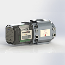
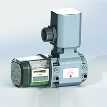
The G Series Roots flowmeter (Type M) is mainly applicable to the measurement of gas consumption by small and medium business user, which integrates the functions of machinery, termperature and pressure correction, remote transmission, recharge, valve control and other functions. It has an exclusive invention patent; and the product is exquisite and beautiful in appearance, whose performance is leading position in the industry, with a variety of specification.
The product’s mechanical performance is stable. Range ratio can reach 1:100.
Initial flow rate is 0.01m³/h. Intergrated mechanical counting, temperature and pressure correction, remote transmission, recharge, valve control into one assembly.
Integrated circuit and low efficiency design.
The battary life can last more than 3 years, and the memery can store data for 27 months ( a set of data per hour).
Description
Unit
G6
G10
G16
G25
Flow Range
m3/h
0.1-10
0.16-16
0.25-25
0.4-40
Accuracy
級
1.0/1.5
1.0/1.5
1.0/1.5
1.0/1.5
Diameter (thread)
mm
DN20/25/32
DN20/25/32
DN20/25/32
DN20/25/32
Working Pressure
MPa
1.2
1.2
1.2
1.2
Max Working Presssure
kPa
50kPa
50kPa
50kPa
50kPa
Pressure Loss
kPa
0.25kPa
0.25kPa
0.25kPa
0.25kPa
Distance (In& out )
mm
104
104
104
104
Length
mm
223
223
251
279
Highth
mm
150
150
150
150
Path DN (mm)DN(mm)
Model specification
A
A1
H1
B
Threaded connection
Flange connection
H
G
H
D
K
n
d
DN25
G10
195
60
104
100
182
1”
171
115
80
4
14
G16
227
76
104
100
182
1”
171
115
80
4
14
G25
261
93
104
100
182
1”
171
140
100
4
18
DN32
G10
195
60
104
100
182
1¼”
171
140
100
4
18
G16
227
76
104
100
182
1¼”
171
140
100
4
18
G25
261
93
104
100
182
1¼”
171
140
100
4
18
DN40
G10
195
60
104
100
182
1¼”
171
140
100
4
18
G16
227
76
104
100
182
1¼”
171
140
100
4
18
G25
261
93
104
100
182
1¼”
171
140
100
4
18
Note: pipeline through DN, thread connection size and flange joint size can also be provided according to user requirements.
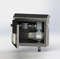
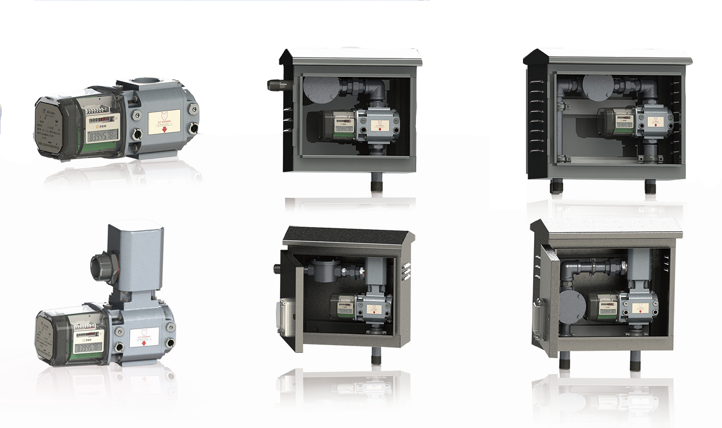
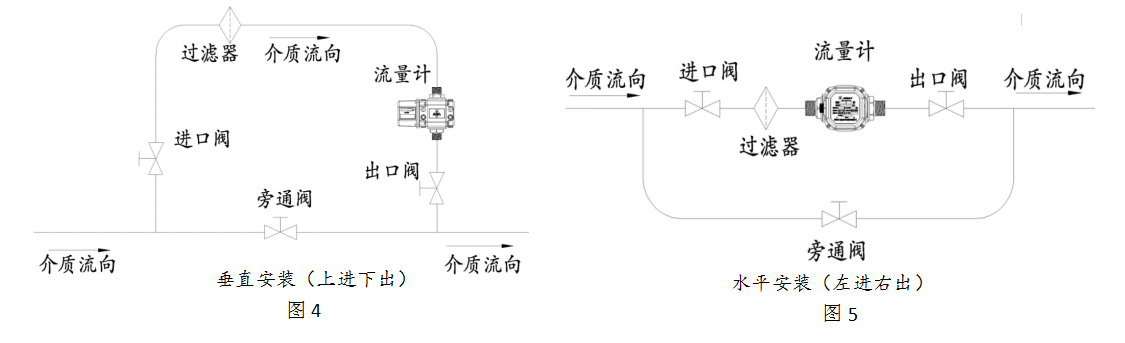
There are two ways to install flowmeters: vertical installation and horizontal installation (Fig. 4, Fig. 5). Vertical installation is recommended. When the flowmeter is installed vertically, the inlet end of the medium should be above and the air flow should flow from top to bottom, so that the rotor has self-cleaning ability to the dirt. When installed horizontally, the axis of the inlet and outlet end of the flowmeter should not be lower than the axis of the pipeline, so as to avoid the dirty impurities in the medium remaining in the flowmeter's flow detection chamber. Normal speed. When installing, the filter must be arranged upstream of the flowmeter to improve the cleanliness of the medium. (the filter is supplied by our company).
Matters needing attention
1. After the flowmeter has been installed correctly, before entering the normal operation, the corresponding type of lubricating oil should be added to the flowmeter according to the requirements. During the operation, the quality and quantity of oil should be checked regularly, and the lubricating oil should be replaced and supplemented in time to ensure the normal operation of the flowmeter, and the fixed part of the flowmeter should not be loosened at will.
In order to ensure the normal use of flowmeters, attention should be paid to and prevention of overpressure and overflow of flowmeters during operation.
3 field installation and maintenance must turn off external power before opening. And there should be no harmful gas on the site.
Maintenance and battery replacement must be carried out in a safe place. Maintenance can only be carried out when the presence of non-combustible gases is confirmed at the installation site.
When using external power supply, it must be matched with the related equipment (safety grille) identified by the explosion-proof certification authority to form the intrinsic safety explosion-proof system before it can be used in the corresponding explosive dangerous places. The shielded cable is used to connect the cable, and the shielding layer is grounded in a safe place. The distribution parameters of the cable are controlled within 0.05 uF/1mH.
6 users are not allowed to change electrical components in their own products at will. When installing, using and maintaining products, users must abide by the relevant provisions of GB50058-92 "Code for Design of Electric Power Devices in Explosive and Fire Hazardous Environment" and "Code for Electrical Safety in Explosive Hazardous Places of the People's Republic of China".

- Index >
- Product Center >
- G Series Roots flowmeter (Type M) >
Product Center
- Metering box
- Gas converter
- Gas converter
- Monitoring and reading systems
- Internet of things
- Wireless Gas meter
- IC card Gas meter
- MTTM Series Turbine flowmeter
- MTRM Series Roots flowmeter
- G Series Roots flowmeter (Type Y)
- G Series Roots flowmeter (Type M)


Flowmetek (Shanghai) Automation instrument co., LTD. Company reserves all rights. Shanghai ICP:09017634
Address: N0.2199 Guangtai Road ,Shanghai Zip code:201405 Tel:021-57588188