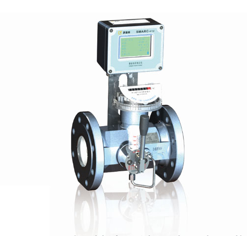
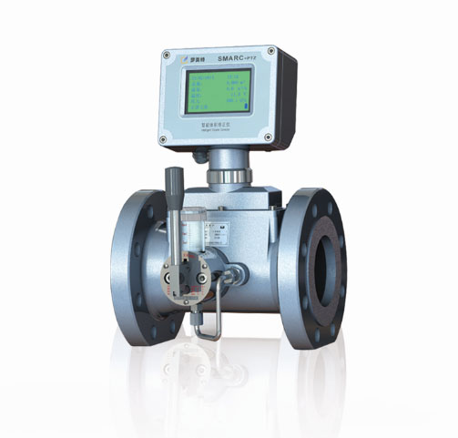
The MTTM Series Turbine flowmeter is a high precision flowmeter, which designed and developed by ourselves on the basis of absorbing the advantages of imported products. The product integrates the functions of machinery, termperature and pressure correction, remote transmission, recharge,valve control into one assembly. The product is mainly used in gas metering for industrial and commercial users.The product is exquisite and beautiful in appearance, whose performance is leading position in the industry, with a variety of specification.
The product’s mechanical performance is stable. Range ratio can reach 1:20.
Intergrated Mechanica counting, temperature and pressure correction, remote transmission, recharge, valve control into one assembly.
The battary life can last more than 3 years
and the memery can store data for 12 months ( a set of data per hour)
The meter head can rotate freely and easy to reading data.
Specification
Flow Range
Flange OD
Pressure Loss
Flange Distance
Length
m3/h
mm
kPa
mm
mm
MTTM-50A(Z)
5~65
DN50
0.6
150
411
MTTM-50B(Z)
8~100
0.9
MTTM-50C(Z)
10~160
2.0
MTTM-80A(Z)
8~160
DN80
0.7
240
439
MTTM-80B(Z)
13~250
1.2
MTTM-80C(Z)
20~400
2.2
MTTM-100A(Z)
13~250
DN100
0.7
300
468
MTTM-100B(Z)
20~400
1.0
MTTM-100C(Z)
32~650
2.3
MTTM-150A(Z)
32·650
DN150
0.7
450
528
MTTM-150B(Z)
50~1000
1.0
MTTM-150C(Z)
80~1600
2.3
MTTM-200A(Z)
50~1000
DN200
0.7
600
595
MTTM-200B(Z)
80~1600
0.9
MTTM-200C(Z)
130~2500
1.7
MTTM-250A(Z)
80~1600
DN250
0.6
750
660
MTTM-250B(Z)
130~2500
1.0
MTTM-250C(Z)
200~4000
2.0
MTTM-300A(Z)
130~2500
DN300
0.7
900
722
MTTM-300B(Z)
200~4000
1.0
MTTM-300C(Z)
320~6500
2.0
Remarks : 1. Nominal pressur: PN1.6Mpa, Standard Pressure sensor 0.5Mpa, any special requirement from customer need to send new request when send orders.
2. All products is according to the requirement of grade 1.5, 1.0.
3. Smart roots flowmeter’s specification has the lettle “Z“and Mechanical flowmeter has no lettle"z"
通經
mm
PN
MPa
A
B
H
D
K
d
n
L
智能
機械
雙顯
DN25
1.6
200
164
318
228
387
115
85
14
4
14
2.5
4.0
DN50
1.6
200
214
344
252
404
165
125
99
4
18
2.5
4.0
DN80
1.6
240
241
374
276
418
200
160
132
8
18
2.5
4.0
DN100
1.6
300
262
393
361
493
220
180
156
8
18
2.5
270
400
369
501
235
190
156
8
22
4.0
DN150
1.6
450
313
457
426
556
285
240
211
8
22
2.5
321
465
434
564
300
250
211
8
26
4.0
DN200
1.6
600
368
501
470
600
340
295
266
12
22
2.5
378
511
480
610
360
310
274
12
26
4.0
386
519
488
618
375
320
284
12
30
DN250
1.6
750
438
572
541
671
405
355
319
12
26
2.5
448
582
551
681
425
370
330
12
30
4.0
460
594
563
693
450
385
345
12
33
DN300
1.6
900
482
627
706
839
460
410
370
12
26
2.5
495
640
719
849
485
430
389
16
30
4.0
515
655
734
864
515
450
409
16
33
- 1: Selection should be within the prescribed flow range to prevent over-speed operation, in order to obtain the desired accuracy and ensure normal service life. (Flowmeters can be damaged by over-speed operation due to pressure testing, purging of pipes or exhaust gas, and the operation of turbines in reverse flow)
2: In order to prevent the pipeline and flowmeter from being damaged by the instantaneous airflow impact, the flowmeter should open the front valve slowly when it is put into operation, and gradually increase the flow rate so as to avoid damaging the turbine by the instantaneous airflow impact. Then slowly open the valve and run for 1 to 2 minutes at a small flow rate. After the flowmeter is in normal operation, all the valves are opened (opening time is not less than 15S). The valve should be slowly closed after closing the valve. Do not shut down suddenly.
3: The number of times to add lubricating oil depends on the cleanliness of the temperament, usually once a month. The specific operation and lubricating oil can be seen in the oil cup label.
4: When the flowmeter is running, it is not allowed to open the back cover or change the internal parameters, otherwise it will affect the normal operation of the flowmeter.
5: If the output signal is 4mA-20mA current signal, in order to improve its accuracy, users should set the corresponding value of 20mA according to the actual maximum standard volume flow value.
6: do not loosen the fixed parts of the flowmeter at will.
7: After installation, air tightness test should be carried out on the pipeline to strictly check the air tightness of the pipeline. For auxiliary technical equipment equipped with pressure compensator, attention should be paid to the pressure range of the pressure testing equipment in order to avoid damaging the pressure measuring components.
8: strictly prohibit the flow meter on-line welding pipe flange.
9: there is no strong external magnetic field disturbance and strong mechanical vibration around the flowmeter.
10: When the flowmeter is installed outdoors, it is suggested to add protective cover to avoid the influence of rainwater immersion and sunshine on the service life of the flowmeter.
11: the flowmeter should be reliably grounded, but it must not be shared with the strong power system ground wire. When installing or overhauling the pipeline, the ground wire of the welding system shall not be overlapped with the flowmeter.
12: In the course of use, users shall not change the connection mode of explosion-proof system and the interface of each lead arbitrarily.
13: When installing, using and maintaining products, users must abide by the relevant provisions of Part 15 of the electrical equipment for explosive gas environment: electrical installation in dangerous places (except coal mines). When the product is used in the "0" zone, the power transformer supplying power to the safety grid shall comply with Article 8.1 of GB3836.4-2000.
14: The product must match with the safety grid identified by the explosion-proof inspection organ to form the intrinsic safety explosion-proof system. The shielded cable is used to connect the cable, and the shielding layer is grounded in the safe place. The distribution parameters of the cable are within 0.2uF/0.3mH.
15: installation and use requirements of intrinsically safe explosion-proof products
The intrinsic safety explosion-proof products equipped with SMARC volume corrector must comply with the following requirements in addition to the precautions for the use of the above-mentioned Article 6.
16: on-site installation and maintenance must turn off the external power before opening.
17: the product shell has earthing terminals, users should be reliably grounded when using products.
18: there should be no harmful gas to the aluminum alloy at the installation site.
19: Maintenance and battery replacement must be carried out in a safe place. Maintenance can only be carried out when the presence of non-combustible gases is confirmed at the installation site.
20: When using external power supply, it must be matched with the related equipment (safety grille) identified by the explosion-proof certification authority to form the intrinsic safety explosion-proof system before it can be used in the corresponding explosive dangerous places. The shielded cable is used to connect the cable, and the shielding layer is grounded in a safe place. The distribution parameters of the cable are controlled within 0.05uf/1mH.
21: Safety grate must be installed in safe place, and its installation, use and maintenance must comply with the relevant provisions of the safety grate instructions.
22: users are not allowed to change electrical components in their own products at will.
23: When installing, using and maintaining products, users must abide by the relevant provisions of GB50058-92 "Code for Design of Electric Power Devices in Explosive and Fire Hazardous Environment" and "Code for Electrical Safety in Explosive Hazardous Places of the People's Republic of China".
24: intrinsically safe hazardous areas below 1 zones for combustible gases of type II B class T4.

- Index >
- Product Center >
- MTTM Series Turbine flowmeter >
Product Center
- Metering box
- Gas converter
- Gas converter
- Monitoring and reading systems
- Internet of things
- Wireless Gas meter
- IC card Gas meter
- MTTM Series Turbine flowmeter
- MTRM Series Roots flowmeter
- G Series Roots flowmeter (Type Y)
- G Series Roots flowmeter (Type M)


Flowmetek (Shanghai) Automation instrument co., LTD. Company reserves all rights. Shanghai ICP:09017634
Address: N0.2199 Guangtai Road ,Shanghai Zip code:201405 Tel:021-57588188