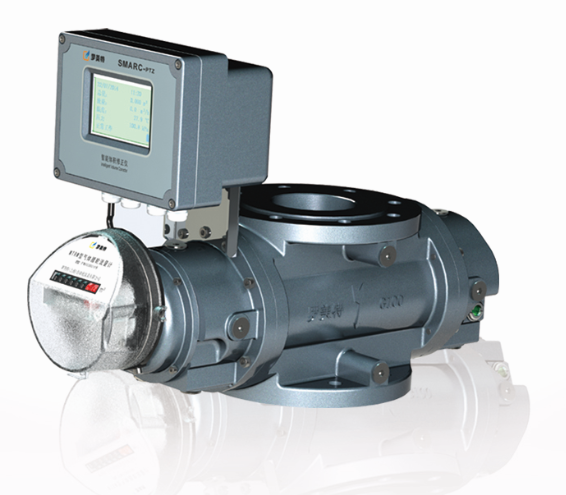
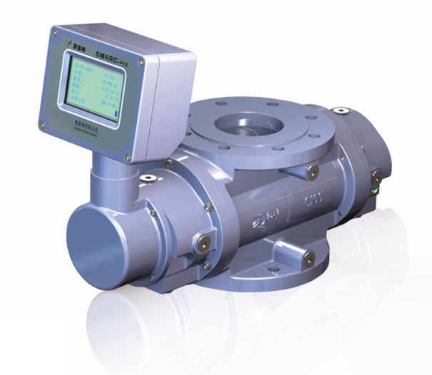
The MTRM Series Roots flowmeter is a wide range and high precision flowmeter, which designed and developed by ourselves on the basis of absorbing the advantages of imported products. The product integrates the functions of machinery, termperature and pressure correction, remote transmission, recharge,valve control into one assembly. The product is mainly used in gas metering for industrial and commercial users.The product is exquisite and beautiful in appearance, whose performance is leading position in the industry, with a variety of specification.
The product’s mechanical performance is stable. Range ratio can reach 1:300. Initial flow rate is 0.04m³/h. Intergrated Mechanica counting, Temperature and Pressure correction, Remote transmission, Recharge, Valve control into one assembly. Integrated circuit and low efficiency design. The battary life can last more than 3 years, and the memery can store data for 12 months ( a set of data per hour). The meter head can rotate freely and easy to reading data
Specificati
Flow Rang
Flange OD
Pressure Loss
Flange Distance
Length
m3/h
mm
kPa
mm
mm
MTRM40A(Z)
0.32-16
DN40
0.1
171
438
MTRM40B(Z)
0.5-25
DN40
0.1
171
438
MTRM40C(Z)
0.5-40
DN40
0.1
171
463
MTRM50A(Z)
0.65-65
DN50
0.15
171
489
MTRM50B(Z)
0.67-100
DN50
0.24
171
545
MTRM80A(Z)
0.8-160
DN80
0.26
171
582
MTRM100A(Z)
1.25-250
DN100
0.32
241
575
MTRM100B(Z)
2-400
DN100
0.53
241
653
MTRM100C(Z)
3.25-650
DN100
0.75
271
744
MTRM150A(Z)
3.5-700
DN150
0.76
406
804
MTRM150B(Z)
5-1000
DN150
0.77
406
920
MTRM200A(Z)
8-1600
DN200
0.78
406
1020
Remarks : 1. Nominal pressur: PN1.6Mpa, standard pressure sensor 0.5Mpa, any special requirement need to send new request when send orders.
2. All products is according to the requirement of grade 1.5, 1.0
3. Smart roots flowmeter’s specification has the lettle “Z” and Mechanical flowmeter has no lettle “Z”.型号
規格
流量
規格
通徑
DN
(mm)
A
A1
H1
H
B
D
K
n
d
一字雙顯
機械
雙顯
一字雙顯
機械
雙顯
雙顯
機械
一體
MTRM-40A
G10
DN40
438
326
142
112
325
140
155
150
110
4
M16×40
MTRM-40B
G16
DN40
438
326
142
112
325
140
155
150
110
4
M16×40
MTRM-40C
G25
DN40
463
351
155
125
325
140
155
150
110
4
M16×40
MTRM-50A
G40
DN50
489
381
170
141
345
171
165
165
125
4
M16×45
MTRM-50B
G65
DN50
545
437
198
169
345
171
165
165
125
4
M16×45
MTRM-80A
G100
DN80
582
474
216
187
345
171
165
200
160
8
M16×45
MTRM-100A
G160
DN100
575
468
214
181
418
241
252
220
180
8
M16×50
MTRM-100B
G250
DN100
653
546
253
220
418
241
252
220
180
8
M16×50
MTRM-100C
G400
DN100
744
637
309
276
418
241
252
220
180
8
M16×50
MTRM-150A
G400
DN150
804
692
304
280
532
406
432
285
240
8
M20×65
MTRM-150B
G650
DN150
920
808
362
337
532
406
432
285
240
8
M20×65
MTRM-200A
G1000
DN200
1020
908
412
387
532
406
432
340
295
12
M20×75
- 1: strictly prohibit the flow meter on-line welding pipe flange.
2: Before and after installation of flowmeter, the pipeline should be purged, and the impurities such as welding slag, iron scraps and sand in the pipeline should be thoroughly removed (special attention should be paid to removing impurities in the elbow of flowmeter before vertical installation), so as to avoid foreign matter entering and damaging the flowmeter, and the inner wall of the pipeline should be clean and free of fouling.
3: In order to facilitate regular maintenance and weekly inspection of flowmeters, it is recommended to set up bypass pipelines (the bypass pipeline valves should be locked in normal operation).
4: before installing the meter, check whether the rotor is flexible.
5: Seals should not be protruded into the pipeline during installation. There is no deviation between the inlet and outlet axes of the flowmeter and the connecting pipeline.
6: When the flowmeter is installed horizontally, it is recommended to install a steel expander (compensator) after the flowmeter. The expander must meet the requirements of nominal diameter and nominal pressure of pipeline design. The telescopic device is used to compensate for the stress of the pipeline and facilitate the installation and disassembly of the flowmeter.
7: After installation, air tightness test should be carried out on the pipeline to strictly check the air tightness of the pipeline. For auxiliary technical equipment equipped with pressure compensator, attention should be paid to the pressure range of the pressure testing equipment in order to avoid damaging the pressure measuring components.
8: When installing the flowmeter, we should pay attention to the flow direction of the flowmeter is consistent with the flow direction of the gas, and strictly examine the use conditions and installation environment conditions of the flowmeter.
9: there is no strong external magnetic field disturbance and strong mechanical vibration around the flowmeter.
10: the flowmeter with volume correction device must be reliably grounded, but it must not be shared with the strong power system ground wire.
11: there should be no corrosive gas to the aluminum alloy at the installation site.
12: When additional power supply is needed, it must be in accordance with the requirements of the corrector, otherwise it will damage the instrument or cause safety problems.
13: After the flowmeter has been installed correctly, before entering the normal operation, the corresponding type of lubricant should be added to the flowmeter according to the requirements, and the quality and quantity of oil should be checked regularly during the operation. Replace and replenish lubricating oil in time to ensure the normal operation of the flowmeter.
14: The valve before and after flowmeter should be opened and closed slowly during operation, so as to avoid sudden change of instantaneous flow rate and damage flowmeter.
15: The operation of upstream gas filters should be checked regularly during operation, and the filter elements should be cleaned or replaced when necessary.
16: In order to ensure the normal use of flowmeters, attention should be paid to and prevention of overpressure and overflow of flowmeters during operation.

- Index >
- Product Center >
- MTRM Series Roots flowmeter >
Product Center
- Metering box
- Gas converter
- Gas converter
- Monitoring and reading systems
- Internet of things
- Wireless Gas meter
- IC card Gas meter
- MTTM Series Turbine flowmeter
- MTRM Series Roots flowmeter
- G Series Roots flowmeter (Type Y)
- G Series Roots flowmeter (Type M)


Flowmetek (Shanghai) Automation instrument co., LTD. Company reserves all rights. Shanghai ICP:09017634
Address: N0.2199 Guangtai Road ,Shanghai Zip code:201405 Tel:021-57588188